A few weeks ago my PCBs for the “Main Unit Shield” came in. Again, OSH Park delivered ahead of schedule and they look great.

Seeing that i’m doing more and more builds with small surface mount parts, I decided to get a hot-air rework station. It turns out that Microcenter down the street carries a cheap unit so i picked one up and got to work. It was actually pretty easy to use. I slobbed solder paste over the pads, placed the part, and applied the heat. After about a minute the tiny solder balls in the paste would start to melt and cling together. The solder mask did its job, all the molten solder blobs found their homes on pads, the part self centered, and voila. It turned out great and was far more forgiving than I would have thought. (or so I thought).
This board was a bit more of a headache than the last board. When i first powered on the board, the ADCs were all over the place. I couldn’t get accurate readings, they should shift and wonder, it was a mess. The only good news was that the I2C pullups and connection out to the dashboard worked fine.
The ADC trouble boiled down to three issues. First, I specified the wrong opamp parts. I designed the ADC input opamp buffers as requiring rail-to-rail input (common mode voltage) and the parts I specified didn’t allow this. I replaced the Microchip MCP604s with TI OPA4342s.
Second, I found a short between two input channels which occurred because i had a via too close to a resistor pad. I removed the solder bridge and filed it away as a lesson learned for the next PCB i layout.
Even after doing the above two fixed, i was getting strange results. I think having the short killed an opamp, so i replaced it. Then that seemed to work, but then the ADC wasn’t reading correctly. I wasn’t sure if it was hardware or software at this point so i broke out the Saleae Logic Analyzer and verified the SPI bus communication. It all looked good. So I ordered more parts, replaced more parts. Still no luck.
Finally I realized that I might be cooking these parts with the heat gun. I had a couple spare parts so I decided to remove the bad parts with hot air, but solder the new ones in with the iron… and it worked. So I spun my wheels for a couple weeks mostly due to my own workmanship mistakes. Looking back on it, i think that rather than blasting the part with heat, i need to more closely mimic the temperature profile of a reflow oven. Ie, warm the board/part up for a few minutes first at a safe temperature, and then relatively quickly ramp up the heat to melt the solder and then drop it back down again.
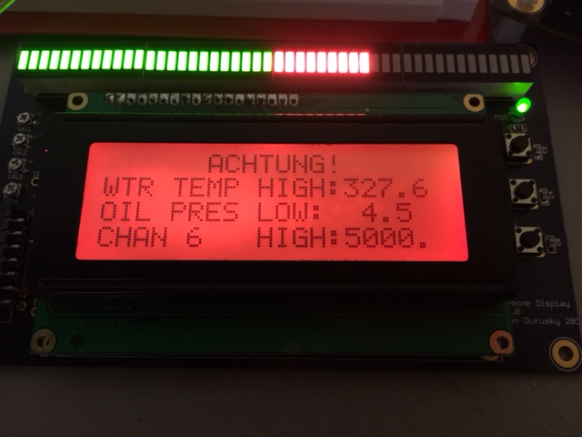
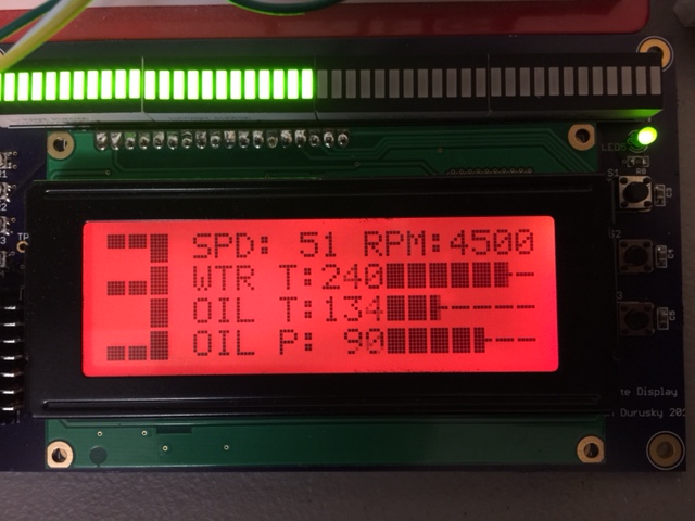
But in the end, the board works.

At this point this prototype hardware is pretty solid. I’ll continue to fine tune the software, but I’m mostly waiting for the M3 to thaw out so I can install the sensors and this unit in the car and do some field testing.