This is the first of a few posts where I’ll break down a certain subsystem of the digital dashboard and explain in more detail. First up: temp sensors.
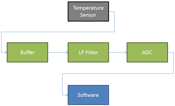
The temperature sensing subsystem consists of a few parts. First is the sensor itself. Then, the circuitry on the PCB consists of a buffer, a filter, and an ADC. Lastly, the digitized input is processed in software on the processor.
For temp sensors, I chose the AEM 30-2012 temperature sensor.
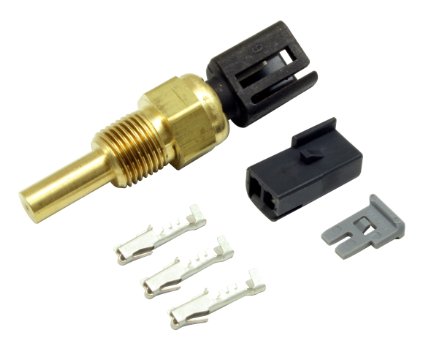 Physically, it is a 1/8″ NPT thread sensor and comes with the mating connector and terminals. I chose this sensor because its fairly cheap at around $40, is quite accurate (+/- 1.5C), and comes with good support and documentation from AEM.
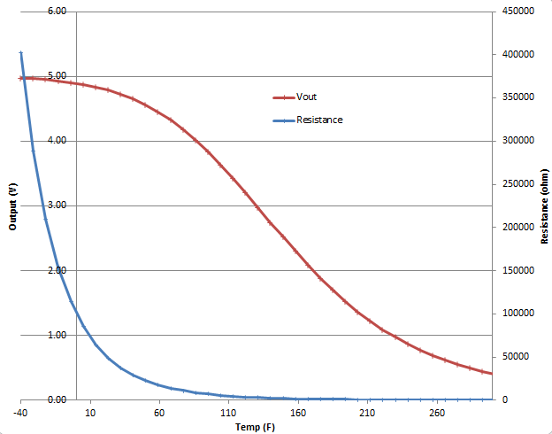
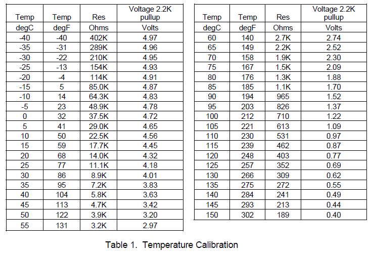
The sensor works as a variable resistor whose resistance varies with temperature. The datasheet provides a nice table showing how the resistance changes over a broad temperature range. This table will be discussed later in the software section.
Next up is the electrical design consisting of the sense circuit, buffering, filtering, and analog-to-digital conversion.
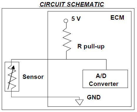
The easiest way to convert a variable resistor to a voltage signal is to put it into a voltage divider using a pull-up resistor. In this configuration, the output voltage will vary with resistance and thus temperature. The AEM 30-2012 datasheet even providers a reference schematic:
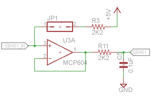
This is the schematic for this part of my board. I’m using a 2.2k resistor for the pull-up (R3). I also put a jumper between the sensor input (SENS1_IN) and this pullup so that i can disable it if i’m using a sensor that provides its own voltage output.
Using this configuration, the voltage will scale from 0-5V according to the temperature by:
SENS1_IN = 5V * ( Rsensor/(Rsensor + Rpullup) )
Once we have a sensor voltage signal, it’s a good idea to buffer it. A buffer provides a high impedance input that won’t load down the sensor. It also provides a low impedance output that is able to drive the next stage. Basically think of it as a divider between the outside world and your processing circuitry. The easiest way to make a buffer is to use an opamp buffer as shown below, U3A.
The next stage is a basic RC low pass filter using R11 and C5. These values create a low pass filter with a cut off at F = 1/(2*Pi*R*C) = 723hz. This is plenty high for most sensors (this circuit is used for all 8 input channels and is intended to be flexible), but is low enough to filter out most unwanted noise.
Next up is the ADC. For this project i chose the 8 channel, 12-bit, Microchip MCP3208. It’s SPI bus makes interfacing with the processor easy. 12 bits provides a max value of 2^12 = 4096 for a range of 0-4095. So each bit represents 5.0V/4096bits = 1.22mV/bit which is more than adequate resolution for this application.
Lastly, we have the software which processes this digital information. Because the temperature sensor is nonlinear, we have to use a lookup table to convert its output voltage (which represents its resistance which represents the temperature) to a temperature. The datasheet gives us:
Here is the table implemented in code using the digital representation of the voltage and degrees C:
// Temp LUT - digital, degC
short tempLUT[39][39] = {
{ 325, 150 },{ 362, 145 },{ 404, 140 },{ 451, 135 },
{ 505, 130 },{ 565, 125 },{ 634, 120 },{ 710, 115 },
{ 796, 110 },{ 892, 105 },{ 1000, 100 },{ 1118, 95 },
{ 1249, 90 },{ 1391, 85 },{ 1544, 80 },{ 1708, 75 },
{ 1882, 70 },{ 2063, 65 },{ 2248, 60 },{ 2435, 55 },
{ 2621, 50 },{ 2803, 45 },{ 2976, 40 },{ 3138, 35 },
{ 3287, 30 },{ 3421, 25 },{ 3540, 20 },{ 3644, 15 },
{ 3732, 10 },{ 3807, 5 },{ 3869, 0 },{ 3920, -5 },
{ 3961, -10 },{ 3993, -15 },{ 4018, -20 },{ 4038, -25 },
{ 4053, -30 },{ 4065, -35 },{ 4074, -40 }};
The following code converts the digitized voltage input to a temperature using the lookup table. First it searches the lookup table for the closest match that less than the input value. The input value must then be between this match and the next one higher. It then linearly interpolates between these two table entries to find the equivalent temperature.
/* Temp Sensor Look Up Table
* Returns Temp in C
*/
float ToTemperature(unsigned short adcIn) {

short lowerI = 0;
short upperI = 0;
for(short i=0; i<39; i++) {
   if(tempLUT[i][0] <= adcIn ){
      lowerI = i;
   }
   else{
      upperI = i;
      break;
   }
}
return tempLUT[lowerI][1] + (float)( tempLUT[upperI][1] - tempLUT[lowerI][1] )*( adcIn - tempLUT[lowerI][0] )/(float)( tempLUT[upperI][0] - tempLUT[lowerI][0] );
}
And that’s about how it works, from sensor to computed value.
