Monthly Archives: March 2015

The M3, rollbars, subframes, cracks…

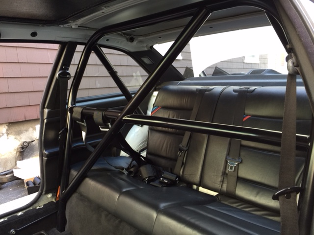
Last fall I was prepping for the install of a bolt-in 4-point roll bar when i noticed a crack under my back seats…

IMG_1114 IMG_1113

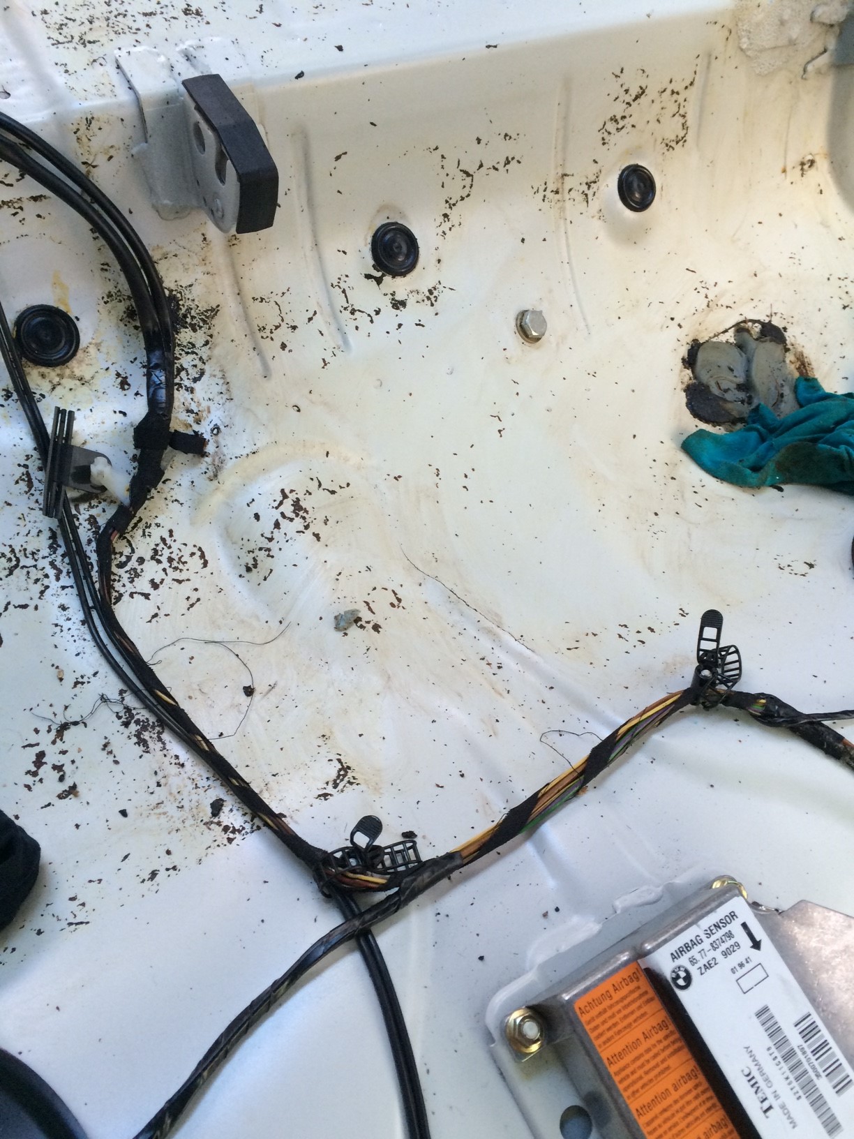
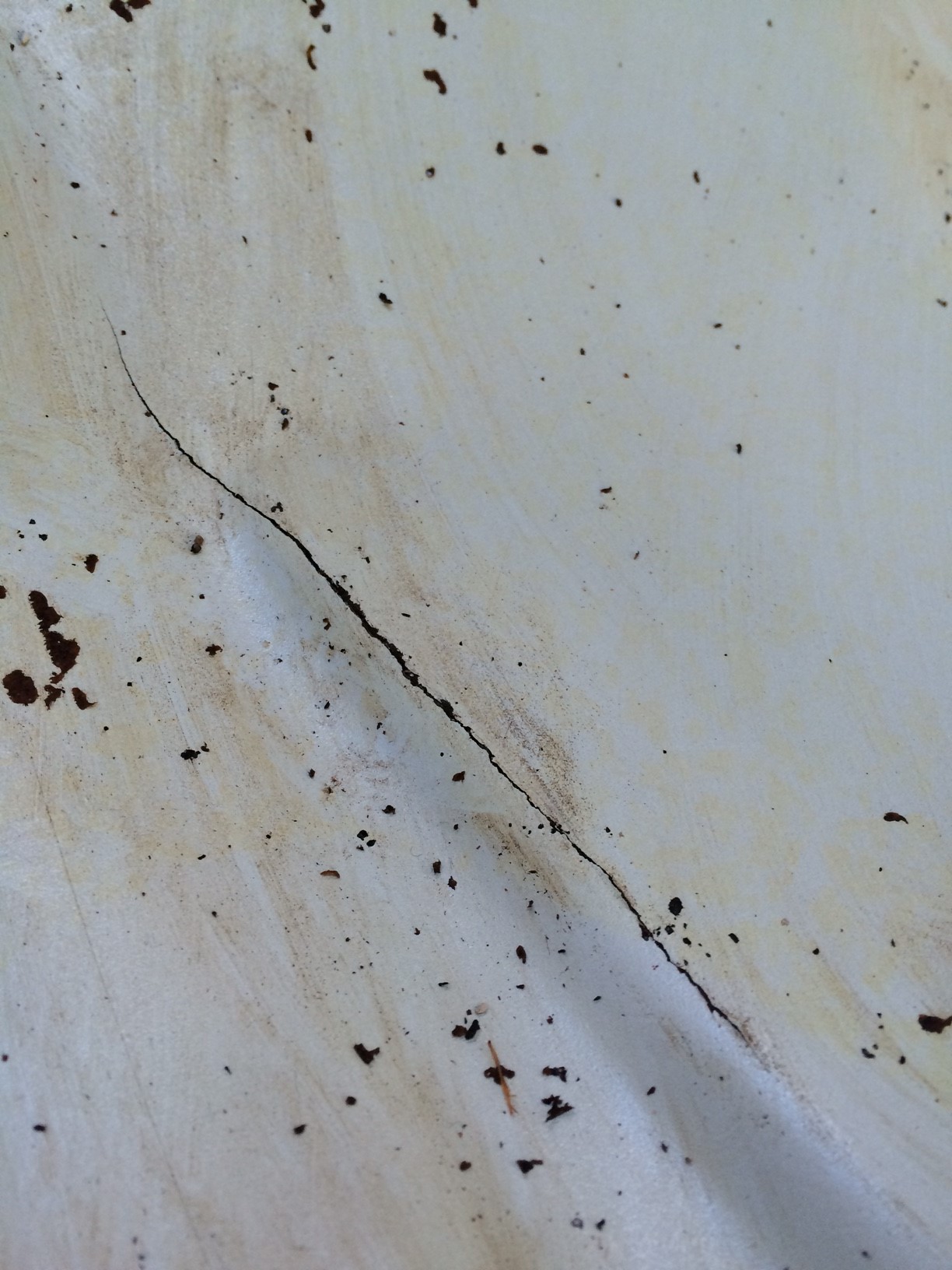
That couldn’t be good so I had an excellent local race shop, Vintage Sports & Restoration, take a look. And they found a cracked subframe.

image2_small image1_small


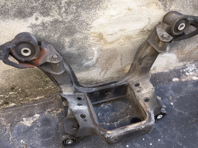
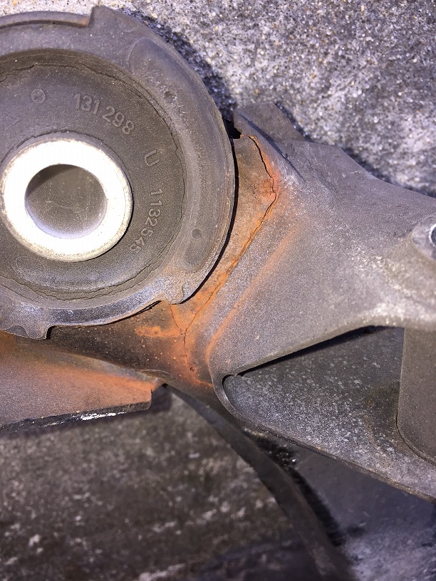
This is a fairly uncommon failure on an E36. Typically it is the stubframe *mounts*, which are a part of the unibody of the car, that crack. My mounts were fine, but it was this ear of the subframe itself that cracked.

The shop also noticed that the previous owner had installed solid aluminum differential mounts, but kept the original rubber subframe mounts in place. With no isolation between the diff and the subframe, all that driveline energy was being applied to the rubber bushings. They quickly died and eventually fatigued the subframe and it cracked. At the point, the driveline energy was being coupled to the unibody asymmetrically through three instead of the four mounting points and that probably caused the stress crack under the seats. So the moral of the story is to understand how bushings/mounts work and make sure they’re being used as a system.

So VSR installed a new freshly painted subframe with 75D mounts. Being the foundation of the rear suspension, we wanted a firm interface here. We opted against going full aluminum because we do want to reduce some of the high frequency energy that can be rough on a street driven car both in sound and metal fatigue.

We then used 95A poly diff mounts so that there is some give to the driveline, but it it still much stiffer than stock to sharpen the response a bit.

If that wasn’t enough, the shop said my diff was making a lot of noise and the left side output shaft bearing was shot. That snow balled into a brand new 3.46 2-clutch, 40%, 45/45 LSD from Dan at diffsonline.com. Dan’s work is top notch and his diffs are very common among the club racers. I rebuilt the LSD in my old E30, but I decided to let the pros handle this one.  Since the car is still driven to and from tracks as far a way as 6-9 hrs, I chose the 3.46. The more racey 3.64 is perfect for a trailered race car but it revs too high for comfortable highway driving.

So as of yesterday the car is home again. Here’s a final rundown of what’s new:

  • 4-pt bolt-in roll bar with custom harness bar height (I’m tall)
  • Repaired crack under rear seats
  • Refurbished subframe w/ AKG 75D bushings
  • Rebuilt 3.46 LSD from diffsonline.com. 95A bushings

IMG_1306

Next up is:

  • Install seats (Cobra Suzukas w/ VAC hardware)
  • Install harnesses (Schroth ProFi 6-pts)
  • Install new valve cover gasket (I have quite a leak now) and spark plugs
  • Install oil temp, water temp, oil pressure sensors (for digital dashboard)
  • Break in new diff!


Digital Dashboard – Shield is up!

A few weeks ago my PCBs for the “Main Unit Shield” came in. Again, OSH Park delivered ahead of schedule and they look great.

shieldpcb


Seeing that i’m doing more and more builds with small surface mount parts, I decided to get a hot-air rework station. It turns out that Microcenter down the street carries a cheap unit so i picked one up and got to work. It was actually pretty easy to use. I slobbed solder paste over the pads, placed the part, and applied the heat. After about a minute the tiny solder balls in the paste would start to melt and cling together. The solder mask did its job, all the molten solder blobs found their homes on pads, the part self centered, and voila. It turned out great and was far more forgiving than I would have thought. (or so I thought).

This board was a bit more of a headache than the last board. When i first powered on the board, the ADCs were all over the place. I couldn’t get accurate readings, they should shift and wonder, it was a mess. The only good news was that the I2C pullups and connection out to the dashboard worked fine.

The ADC trouble boiled down to three issues. First, I specified the wrong opamp parts. I designed the ADC input opamp buffers as requiring rail-to-rail input (common mode voltage) and the parts I specified didn’t allow this. I replaced the Microchip MCP604s with TI OPA4342s.

Second, I found a short between two input channels which occurred because i had a via too close to a resistor pad. I removed the solder bridge and filed it away as a lesson learned for the next PCB i layout.

Even after doing the above two fixed, i was getting strange results. I think having the short killed an opamp, so i replaced it. Then that seemed to work, but then the ADC wasn’t reading correctly. I wasn’t sure if it was hardware or software at this point so i broke out the Saleae Logic Analyzer and verified the SPI bus communication. It all looked good. So I ordered more parts, replaced more parts. Still no luck.

Finally I realized that I might be cooking these parts with the heat gun. I had a couple spare parts so I decided to remove the bad parts with hot air, but solder the new ones in with the iron… and it worked. So I spun my wheels for a couple weeks mostly due to my own workmanship mistakes. Looking back on it, i think that rather than blasting the part with heat, i need to more closely mimic the temperature profile of a reflow oven. Ie, warm the board/part up for a few minutes first at a safe temperature, and then relatively quickly ramp up the heat to melt the solder and then drop it back down again.

But in the end, the board works.

shield

At this point this prototype hardware is pretty solid. I’ll continue to fine tune the software, but I’m mostly waiting for the M3 to thaw out so I can install the sensors and this unit in the car and do some field testing.