I finally got moving again on the digital dashboard project. I was held up a bit not being able to find device models using DipTrace. I made a few from scratch, but it was tedious and was bogging me down. I also knew that when it came time to do the layout, I’d have to shell out for a paid version of DipTrace. This got me researching options and I finally decided to give Eagle another go. It has a clunky UI, but the community support can’t be beat. There are libraries for everything out there. For example Adafruit and Sparkfun both share their schematics in Eagle and offer their libraries up for public use.
After about 30 minutes of getting used to the UI, I was rolling. I was able to find a few obscure device models such as the 12 LED bargraph in the Adafruit library. I also found that making new device models from scratch was a breeze in Eagle so I soon found myself cranking them out myself rather than hunting for them.
Using Eagle, i was able to finalize the design for the remote display PCB. This will serve as the “dashboard” part of this project. The other half will be the “main unit” where the processor is housed along with all the sensor inputs, etc.
Due to all the LED and LCD I/O, I decided to go with a four layer board. It costs twice as much, but everything is neater and more electrically sound. There isn’t much too critical with regards to signal speed or integrity on this board, but its still fun to do things right.
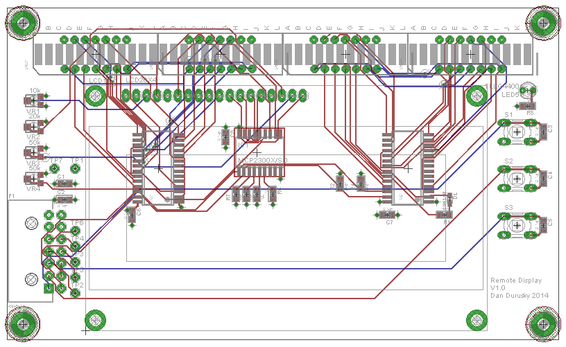
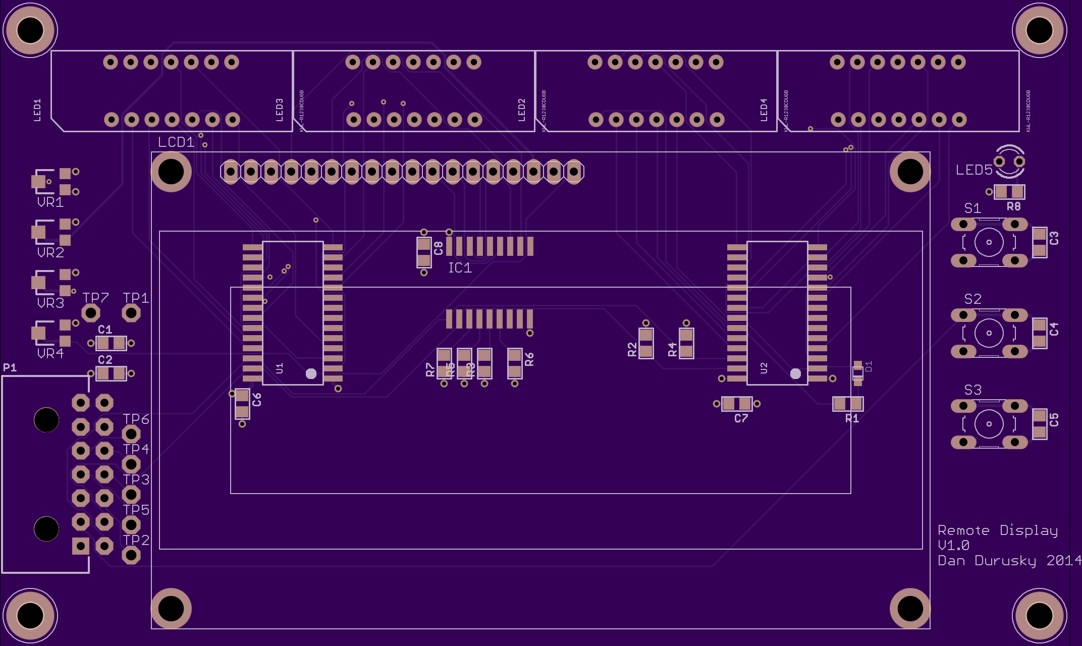
5V power and ground planes are on the inner layers with traces on the outter layers. All components are on top. You can see the four 12 bar LEDs along the top that will act together as the shift light and also blink warning statuses. In the middle is a good old fashioned 20×4 character LCD. It has an RGB backlight so the four trim pots on the left control its contract and background color. On the right are three push buttons. As of now the top button is to start/stop data logging and the other two are for menu scrolling. The connector on the left is a Molex Microfit which is easy to use, has good density, and has cheap off-brand crimp tooling.
The middle chip is the MCP23008 demux that is running the LCD off the I2C bus. The two chips toward the outside are HT16K33 LED controllers and each drive a pair of the 12bar LEDs on the I2C bus as well. Oh and there’s a power LED too!
I decided to go with OSH Park for the PCBs. They have a ton of great feedback and good prices as well. In about two weeks i should have my boards!
I’ll get the parts on order soon and if all goes well, I’ll have a functioning PCB assembly in the next few weeks. My plan is to use this assembly with the LPC4088 dev base board acting as the main unit. This way I’m only introducing one major variable at a time. When all the kinks are worked out with this Remote Display assembly, I’ll move on to ordering the Main Unit boards.