Category Archives: Electronics & Robotics

Digital Dashboard – The Remote Display is Built

I received the “Remote Display” PCBs from OSHPark before Christmas. This was my first time using OSHPark, but i must say it was a pretty great experience. It was very easy to upload my Eagle board design, it processed quickly, and they gave detailed renders of the final boards and all the layers – all easily viewable right on their website. They also arrived ahead of schedule.

IMG_1223
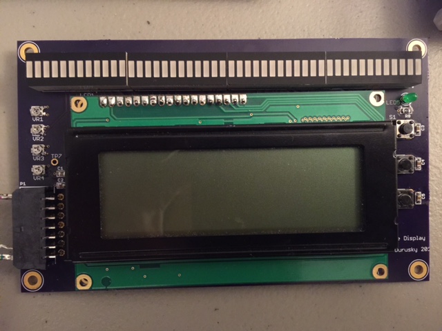
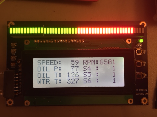
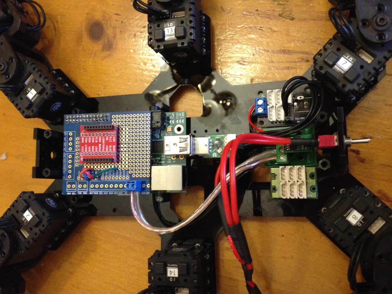
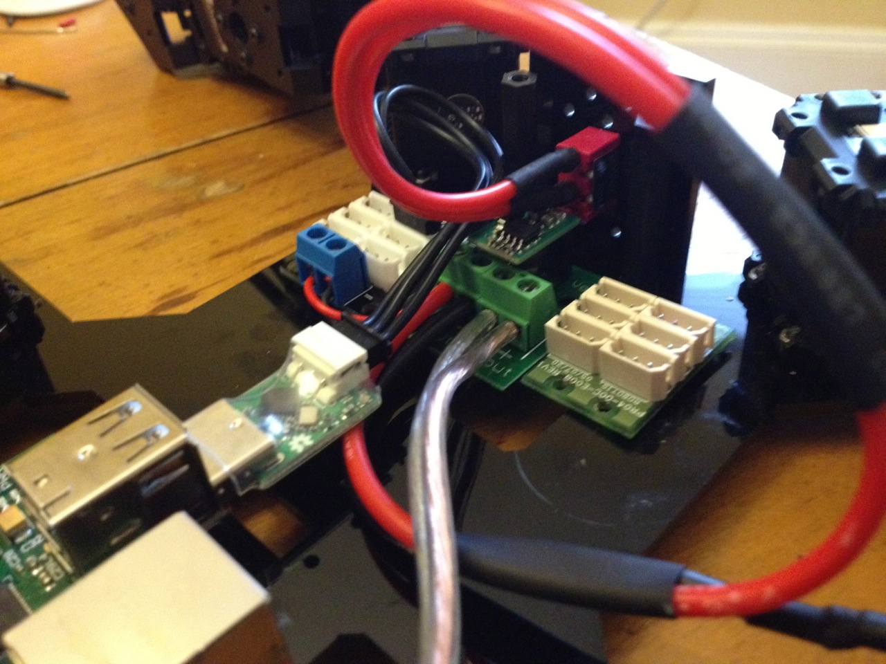
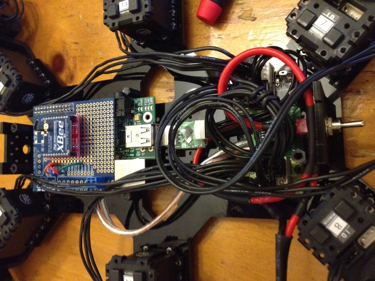
I had some time off for the holidays and managed to get one board built up.

image3

It’s funny how I already see things that I wish I had done differently. Why didn’t i label the trim pots and the buttons?!? (The pots control contrast and the R, G, and B backlight). But what matters most came through, it works!

image2

It still looks like a science fair project, but at least all the hardware is set and physically stable. One less bread board to deal with.

Now that this is done I need to focus on both the “Main Unit” PCB and polish up the software.


PCBs for the digital dashboard!

I finally got moving again on the digital dashboard project. I was held up a bit not being able to find device models using DipTrace. I made a few from scratch, but it was tedious and was bogging me down. I also knew that when it came time to do the layout, I’d have to shell out for a paid version of DipTrace. This got me researching options and I finally decided to give Eagle another go. It has a clunky UI, but the community support can’t be beat. There are libraries for everything out there. For example Adafruit and Sparkfun both share their schematics in Eagle and offer their libraries up for public use.

After about 30 minutes of getting used to the UI, I was rolling. I was able to find a few obscure device models such as the 12 LED bargraph in the Adafruit library. I also found that making new device models from scratch was a breeze in Eagle so I soon found myself cranking them out myself rather than hunting for them.

Using Eagle, i was able to finalize the design for the remote display PCB. This will serve as the “dashboard” part of this project. The other half will be the “main unit” where the processor is housed along with all the sensor inputs, etc.

Due to all the LED and LCD I/O, I decided to go with a four layer board. It costs twice as much, but everything is neater and more electrically sound. There isn’t much too critical with regards to signal speed or integrity on this board, but its still fun to do things right.

Layout


5V power and ground planes are on the inner layers with traces on the outter layers. All components are on top. You can see the four 12 bar LEDs along the top that will act together as the shift light and also blink warning statuses. In the middle is a good old fashioned 20×4 character LCD. It has an RGB backlight so the four trim pots on the left control its contract and background color. On the right are three push buttons. As of now the top button is to start/stop data logging and the other two are for menu scrolling. The connector on the left is a Molex Microfit which is easy to use, has good density, and has cheap off-brand crimp tooling.

The middle chip is the MCP23008 demux that is running the LCD off the I2C bus. The two chips toward the outside are HT16K33 LED controllers and each drive a pair of the 12bar LEDs on the I2C bus as well. Oh and there’s a power LED too!

I decided to go with OSH Park for the PCBs. They have a ton of great feedback and good prices as well. In about two weeks i should have my boards!

top

I’ll get the parts on order soon and if all goes well, I’ll have a functioning PCB assembly in the next few weeks. My plan is to use this assembly with the LPC4088 dev base board acting as the main unit. This way I’m only introducing one major variable at a time. When all the kinks are worked out with this Remote Display assembly, I’ll move on to ordering the Main Unit boards.

Digital Dashboard & Data Logger

For awhile I’ve thought that it’d be cool to make my own digital dash and data logger for my track cars. You can certainly buy these, but they aren’t cheap. I think i can build one for way less, learn a thing or two, and have fun doing it.

So far i have a breadboarded prototype up and running. It’s based on the EA LPC4088 on the mbed.org platform. I’m using a mini dev board for break out and a standard breadboard to host my peripherals.

Prototype!

Prototype!

For now I’m using a basic 20×4 LCD for display. This processor can power a TFT so eventually i may move to that. When in use, i plan to focus more on the shift lights (shown on the right of the breadboard) and warning lights for real time feedback.

Basic Block Diagram

Basic Block Diagram

As of now it has:

  • LPC4088 quickstart board with EA Basic Dev Board
  • LCD with i2c backpack
  • Shiftlight strips (from adafruit) on i2c backpack
  • AD7490 ADC on SPI bus
  • AEM pressure and temp sensors feeding into ADC
  • SD memory card reader on Dev Board

It’s currently capable of receiving sensor inputs via 5V ADC and pulse train (engine and vehicle speed). It crunches the sensor data and displays it on screen. The shift light also functions appropriates and flashes red when max RPM is exceeded. It samples and also writes the data out to the SD memory card at 10hz.

The next step really is to solidify the hardware. I’m working on a schematic that I’ll layout and make into a PCB. It’s mostly done, but i’m hung up on how i want to divide up the components. Should I have a brain in the glove box and a remote display? Should the shift light be separate from the display? etc.  I also have an accelerometer that I need to integrate. Eventually I’ll also want GPS so I should probably make provisions for that before I get too far along. Then again, these things tend to actually develop when you move on what you have now and iterate later. Holding for future updates leads to nothing getting done.

Click on the “Digital Dashboard” category to the right for all the latest posts.

New Processor: Robotis OpenCM9.04 w/ ARM Cortex M3

The last “brain” BETH had was a Raspberry Pi. The Pi worked well and was of course very powerful, but I started to get sick of it.

Having to power on, wait a minute for boot, SSH in, samba share my source files, run program, issue shutdown command, wait for shutdown, and power off all the time got old. I tried to improve things by hooking up an LCD that would run a start up menu on boot up. It would show me the IP address so i could remote-in easier and allow me to run the BETH program with a button press. It helped, but ultimately all it was doing was adding ever more complexity to both hardware and software. I began to realize that all of this was slowing down development because I often didn’t feel like going through the hoops to get started. (boo hoo, right?)

Another con to the Raspberry Pi was that relative to a microcontroller, it used a lot of power and battery life was much less than what it was with the Arbotix microcontroller.

Lastly, I no longer wanted to deal with the Linux overhead. Robot projects are fun, Linux projects are fun, but i’d rather keep them separate so i can focus on one thing at a time.

So all this drove me to find a new processor. The timing was right, though, because Robotis just released the OpenCM9.04.

Robotis OpenCM 9.04

Robotis OpenCM 9.04

This is a totally open-source ARM Cortex M3 based microcontroller designed for use with Dynamixel servos and general robotics use. It uses what’s essentially the Arduino IDE with an ARM toolchain hooked up. It’s very easy to use with the built in 3-pin Dynamixel connectors, voltage regulator, and 3 UARTs. For hardware, all I i had to do was run power, ground, TX, and RX to an Xbee break out board. The board is powered from my powered Dynamixel hub through the Dynamixel connector. The other nice thing is that this board is quite small, about half the size of the original Arbotix controller, and allows my to install the battery back inside the hex body.

For software, I reverted back to my Arduino BETH code, updated to my more recent Raspberry Pi trajectory/gait algorithms, and had it all running in a couple hours. The functioning code is on my GitHub.

I must say its refreshing to have an “instant-on” robot. It makes it much easier to casually boot up and work on it without having to commit for a few hours due to booting up, software updates, remote logins, etc. It’s also nice to focus purely on the software that is controlling the robot directly.

As for power, this is significantly more powerful than the ol AVR in the Arbotix controller (72MHz vs 16MHz, 32bit vs 8bit, etc). The only thing this lacks is a hardware FPU for floating point math. I think this will cut it for my FK/IK/trajectory type needs for now. I do have an upcoming project that may push this limit, but more on that later.

Videos of B.E.T.H.!

I’ve been really slack about ironing out the last few bugs and taking some video of B.E.T.H. in action… But here it is! Some of the movements are a little erratic, but that’s because i’m filming with one hand while controlling the dual joystick controller with the other.

Here is a body forward kinematics demo. Here you can see that i can input body angles via the controller and the legs move as necessary to allow the body rotation without moving the feet.

Next is the tripod gait. This is a simple and fast gait in which two sets of three legs forming a triangle move alternately.

This is a wave gait. The wave gait is slow and moves only one foot at a time. The rest of the legs have to pull backwards in unison.

Finally, we have my favorite, the ripple gait. Two legs move at a time with one leg beginning to step as the other hits it’s peak height in the step. Because two legs move at once, its faster than the wave gait, but slower than the tripod.

For more info on gaits, here is a good article from Oricom Tech. My final code used here is available on my GitHub.

For more info on B.E.T.H., head back to the beginning.

Raspberry Pi Hardware Integration

A few weeks ago I got a Raspberry Pi to run in B.E.T.H. I had been running it all strewn around on the desk, but yesterday I finally got it all packed inside the chassis. Here’s a run down of what I did.

Parts:

IMG_0592

So as you can see, I mounted the Xbee breakout on the Pi Proto Plate. At first the Plate was sitting up too tall. It originally was the full length of the Raspberry Pi and spaced up enough using an extended header that it covered the ethernet and USB ports. I ended up cutting the board down and mounting it on a standard height header so it could sit lower. I mounted the Pi by glue gunning it to plastic standoffs which screw into the chassis.

IMG_0590

As for power, I’m running the battery power into the regulator breakout board and using it as a distribution block to jumper battery power to the power Dynamixel hub. The 5V output of the regulator goes to the Raspberry Pi. I’m powering the Pi through the GPIO power pins accessed through the Pi Proto Plate.

IMG_0594

I plan to order shorter Dynamixel cables and shorten up the battery/switch wires to clean things up, but as of now it looks like this:

IMG_0598

Unfortunately the battery has to go on top of the robot. I now run the wifi adapter and USB2AX in the Pi’s USB ports. I then SSH and/or VNC in over the network to work on bot. If i have to I can reach in and plug a USB hub cable in in place of the wifi adapter.

Back to B.E.T.H.’s main index.

Phase 4: Foot Trajectory Planning and Gait Sequencing Part II

In the previous post, I went over my initial linear approach to stepping and why it didn’t work out so well. This post outlines my current method which is working much better.

The new method uses a sinusoidal “arch” shaped step in the ZX plane. This also works out well since a single sine function can cover the raise and lower part of the step in one time segment. By using a sinusoidal function for the front-to-back stepping in the X direction as well, i could cut the number of case in half to just two. The final benefit is that it produces a very smooth and natural motion with the smooth curves and foot speeds. Here’s what step code looks like:

switch (caseStep[legNum]){

                case 1: //forward raise and lower

                    leg[legNum].footPos.x = -amplitudeX*cos(M_PI*tick/numTicks);
                    leg[legNum].footPos.y = -amplitudeY*cos(M_PI*tick/numTicks);
                    leg[legNum].footPos.z = -abs(amplitudeZ)*sin(M_PI*tick/numTicks);

                    if( tick >= numTicks-1 ) caseStep[legNum] = 2;
                    break;

                case 2: // pull back

                    leg[legNum].footPos.x = amplitudeX*cos(M_PI*tick/numTicks);
                    leg[legNum].footPos.y = amplitudeY*cos(M_PI*tick/numTicks);
                    leg[legNum].footPos.z = 0;

                    if( tick >= numTicks-1 ) caseStep[legNum] = 1;
                    break;

          }// end of case statement

As you noticed, the sequencing itself is carried out by the case statement block. They key to the sequencing is in the caseStep[] array. The array has six elements, one for each leg. The variable defines at which case each leg begins. For a tripod gait, the front right leg (#1), rear right (#3), and middle left (#5) leg all start at the first case and step together. The other legs start 180deg off which is the second case. So for my prior four-case linear “triangle” step function, caseStep[] is defined as {1,3,1,3,1,3}. For the new two-case “sine” step function, caseStep[] is defined as {1,2,1,2,1,2}.

Each case statement increments caseStep[] to the next case in order to advance to the next portion of the foot step. The final code looks like:

/*************************************************
  tripodGaitSine()

**************************************************/
void tripodGaitSine(){

    float sinRotZ, cosRotZ;
    int totalX, totalY;
    float rotSpeedOffsetX[6], rotSpeedOffsetY[6];
    float amplitudeX, amplitudeY, amplitudeZ;
    int duration;
    int numTicks;
    int speedX, speedY, speedR;

    if( (abs(commanderInput.Xspeed) > 5) || (abs(commanderInput.Yspeed) > 5) || (abs(commanderInput.Rspeed) > 5 ) ){

        duration = 500;                               //duration of one step cycle (ms)
        numTicks = round(duration / SERVO_UPDATE_PERIOD / 2.0); //total ticks divided into the two cases

        speedX = 180*commanderInput.Xspeed/127;        //180mm/s top speed for 180mmm stride in one sec
        speedY = 180*commanderInput.Yspeed/127;        //180mm/s top speed
        speedR = 40*commanderInput.Rspeed/127;         //40deg/s top rotation speed

        sinRotZ = sin(radians(speedR));
        cosRotZ = cos(radians(speedR));

        for( int legNum=0; legNum<6; legNum++){                        totalX = leg[legNum].initialFootPos.x + leg[legNum].legBasePos.x;              totalY = leg[legNum].initialFootPos.y + leg[legNum].legBasePos.y;                          rotSpeedOffsetX[legNum] = totalY*sinRotZ + totalX*cosRotZ - totalX;               rotSpeedOffsetY[legNum] = totalY*cosRotZ - totalX*sinRotZ - totalY;                           if( abs(speedX + rotSpeedOffsetX[legNum]) > abs(speedY + rotSpeedOffsetY[legNum]) )
		amplitudeZ = ((speedX + rotSpeedOffsetX[legNum])*duration/3000.0);
            else
		amplitudeZ = ((speedY + rotSpeedOffsetY[legNum])*duration/3000.0);

            amplitudeX = ((speedX + rotSpeedOffsetX[legNum])*duration/2000.0);
            amplitudeY = ((speedY + rotSpeedOffsetY[legNum])*duration/2000.0);

            switch (caseStep[legNum]){

                case 1: //forward raise and lower

                    leg[legNum].footPos.x = -amplitudeX*cos(M_PI*tick/numTicks);
                    leg[legNum].footPos.y = -amplitudeY*cos(M_PI*tick/numTicks);
                    leg[legNum].footPos.z = -abs(amplitudeZ)*sin(M_PI*tick/numTicks);

                    if( tick >= numTicks-1 ) caseStep[legNum] = 2;
                    break;

                case 2: // pull back

                    leg[legNum].footPos.x = amplitudeX*cos(M_PI*tick/numTicks);
                    leg[legNum].footPos.y = amplitudeY*cos(M_PI*tick/numTicks);
                    leg[legNum].footPos.z = 0;

                    if( tick >= numTicks-1 ) caseStep[legNum] = 1;
                    break;

          }// end of case statement

        }// end of loop over legs
        if (tick < numTicks-1) tick++;
        else tick = 0;

    }//end if joystick active

}

I think it needs a little fine tuning of the speeds and step durations, but its essentially done. B.E.T.H. is now fully mobile!

Check out where this all began.

Phase 4: Foot Trajectory Planning and Gait Sequencing Part I

Thanks to my handy IK engine, I no longer need to think in terms of joint angles. All i need to do is move the tip of the foot around in 3D space using the footPos.x, footPos.y, and footPos.z variables.   Stepping is really as simple as looping and incrementing them in such a way to produce the desired movement. Incrementing X moves the foot in the forward X direction. Incrementing X and Y at the same time moves the foot on that diagonal, etc.

I’ve been putting this post off for awhile because I keep changing how I’m implementing the foot stepping. I’ll go through the history for learning’s sake.

At first I was using linear equations to “draw” straight lines with the foot. A foot would step diagonally up and forward, down and forward, then pull back along the ground in the shape of a triangle.


            switch (caseStep[legNum]){

                case 1: //forward raise

                    leg[legNum].footPos.x = ((long)(speedX + strideRotOffsetX[legNum])*tick*SERVO_UPDATE_PERIOD)/duration - (speedX + strideRotOffsetX[legNum])/4;
                    leg[legNum].footPos.y = ((long)(speedY + strideRotOffsetY[legNum])*tick*SERVO_UPDATE_PERIOD)/duration - (speedY + strideRotOffsetY[legNum])/4;
                    leg[legNum].footPos.z = ((long)height*tick*SERVO_UPDATE_PERIOD)/(duration/4);

                    if( tick >= numTicks-1 ) caseStep[legNum] = 2;
                    break;

                case 2: // forward lower

                    leg[legNum].footPos.x = ((long)(speedX + strideRotOffsetX[legNum])*tick*SERVO_UPDATE_PERIOD)/duration;
                    leg[legNum].footPos.y = ((long)(speedY + strideRotOffsetY[legNum])*tick*SERVO_UPDATE_PERIOD)/duration;
                    leg[legNum].footPos.z = height - ((long)height*tick*SERVO_UPDATE_PERIOD)/(duration/4);

                    if( tick >= numTicks-1 ) caseStep[legNum] = 3;
                    break;

                case 3: // down pull back

                    leg[legNum].footPos.x = -((long)(speedX + strideRotOffsetX[legNum])*tick*SERVO_UPDATE_PERIOD)/duration + (speedX + strideRotOffsetX[legNum])/4;
                    leg[legNum].footPos.y = -((long)(speedY + strideRotOffsetY[legNum])*tick*SERVO_UPDATE_PERIOD)/duration + (speedY + strideRotOffsetY[legNum])/4;
                    leg[legNum].footPos.z = 0;

                    if( tick >= numTicks-1 ) caseStep[legNum] = 4;
                    break;

                case 4: // down pull back

                    leg[legNum].footPos.x = -((long)(speedX + strideRotOffsetX[legNum])*tick*SERVO_UPDATE_PERIOD)/duration;
                    leg[legNum].footPos.y = -((long)(speedY + strideRotOffsetY[legNum])*tick*SERVO_UPDATE_PERIOD)/duration;
                    leg[legNum].footPos.z = 0;

                    if( tick >= numTicks-1 ) caseStep[legNum] = 1;
                    break;

          }// end of case statement

This worked well and was fast to process on the Arduino, but it had a couple of issues. First, the leg movement looked a little rigid and unnatural. Sort of jerky with the sudden direction changes. Second and most importantly, the robot wasn’t walking smoothly forward. It would sort of stutter as it moved continuously in a direction. I realized that this was because the foot was coming down and hitting the ground in the opposite direction to travel. This caused a momentary halt in the forward momentum before the foot began to pull backwards. The foot should at least be coming straight down toward the ground before pulling back. I’ll explain how I do this once its ready for prime time.

To be continued in Part II!

Jump back to the beginning of Project B.E.T.H.

B.E.T.H.’s New Brain: Raspberry Pi

Half out of future necessity and half out of simply the urge to tinker with something new, I got a Raspberry Pi. I had considered other microcomputers like the Beagle Bone Black, but I decided to go with the Pi because of software/driver maturity and large community. All the peripheral support, drivers, dev tools, etc I’d need for my projects on the Pi has been well sorted out, optimized, and nicely documented. I want to make cool stuff, not be a pioneer of the embedded linux world.

I have a couple of projects in mind for the Pi. The first will be to power my hexapod robot, B.E.T.H. The Pi will have enough grunt to run all my IK and future terrain adaption algorithms as well as do some light machine vision. The second project I think will be a digital dashboard/data logger for my car.

So far i have the Pi up and running pretty well. I’m using the WiringPi libraries to recreate some of the Arduino functions. It was fairly straight forward porting over the original arduino code to C++ on the Pi. I’ve been coding on the Pi directly using the Geany IDE in X. I’m using floating point math to improve accuracy where ever effective.

The overall hardware plan for B.E.T.H. looks like this:

hex

I’m using an Xbee breakout board from Sparkfun to physically connect the Xbee. It only takes power, ground, TX, and RX connected to the Pi’s UART and it works like a champ. Note that the Pi’s UART is configured to run a console output by defualt. You have to disable that functionality before its free to use.

To control the Dynamixel AX-12A servos, I’m using the USB2AX from Xevelabs. Its great due to its small form factor and USB speed optimizations. For software, you use the Robotis Dynamixel SDK.

The BEC is an RC type from Castle Creations. It works perfectly because its small and light, can take up to 25VDC in, and the adjustable output is programmed to 5.1V by default which is perfect for powering the USB hub and Pi. UPDATE: The CC BEC crapped out on me after about 20 minutes. I’m not sure why. I’ve since switched to the Murata switching regulator and it’s been great.

The D-Link DWA-131 USB wifi adapter isn’t necessary for running B.E.T.H., but its needed to SSH/VNC into the Pi or to run the Pi directly and access the network/internet wirelessly. For $20 its worth having. I chose this model because the chipset is supported out of the box by the linux kernel and again, its pretty small.

The last part I needed was a powered Dynamixel hub. This acts as a normal Dynamixel hub but it also provides an easy interface for applying power to the servos. I’ll probably use the set screw terminals as a distribution block for branching power.

My next task is cramming all of this stuff into the hex body!

Phase 3: Body Kinematics, i.e., Body Translation/Rotation with the Feet Planted

The next thing I wanted to accomplish was being able to translate and rotate the body while keeping the feet planted. For now this will simple enable the robot to wiggle around and “dance”, but eventually these movements will be necessary inputs for traversing uneven terrain.

The concept for this is pretty straightforward. If i want the body to translate right while keeping the feet planted, you simply move all the feet to the left relative to the body:

newFootPositionX = initialFootPositionX - translateX
newFootPositionY = initialFootPositionY - translateY
newFootPositionZ = initialFootPositionZ - translateZ

I’m subtracting the translation because the feet are moving opposite the direction i want the body to go in. ‘translateY’ could be an input from your controller. I using the Bioloid Commander library for easy access to the Commander controller inputs.

Rotations aren’t quite as simple. The concept is to take an angular input, and provide the X,Y,Z offsets necessary for each leg to create that body rotation. A perfect job for the rotation matrix!

Rotation Matrices

Here is some good background info on rotation matrices. Its not nearly as hard as it looks. You simply apply one rotation matrix per axis of rotation. I wanted to be able to rotate on all three axis so i strung all three together.

(X,Y,Z)rotated = (X,Y,Z)initial*Rx*Ry*Rz

The angle pheta in each matrix is the input rotation angle for that axis. You do need some sort of software to crunch this up into closed form equations. I used Matlab which can do the symbolic matrix multiplication. Once I got my equations i was able to calculate my (X,Y,Z)rotated offsets and add them into the equations above to get:

newFootPositionX = initialFootPositionX - translateX - rotatedX
newFootPositionY = initialFootPositionY - translateY - rotatedY
newFootPositionZ = initialFootPositionZ - translateZ - rotatedZ

This *almost* works worked perfectly. The issue is that my corner legs were behaving funny. That i realized was because my math wasn’t taking into account their mounting angle.  Basically each corner points 45 degrees out. I need to rotate all my coordinates for these legs and there’s no better tool than… the rotation matrix! This time its easier because this is a single axis rotation so there is only one matrix, Rz.

(X,Y,Z)coxaCorrected = (X,Y,Z)newFootPosition*Rz

Note that the 45deg input is the angle for the front right leg. The right rear leg would be 135deg, the left rear would be 225deg, and the upper left would be 315deg as you go around the clock.

Here’s the code:

/**********************************************************************************************************
    fodyFK()
    Calculates necessary foot position (leg space) to acheive commanded body rotations, translations, and gait inputs
***********************************************************************************************************/
void bodyFK(){

    float sinRotX, cosRotX, sinRotY, cosRotY, sinRotZ, cosRotZ;
    int totalX, totalY, totalZ;
    int tempFootPosX[6], tempFootPosY[6], tempFootPosZ[6];
    int bodyRotOffsetX[6], bodyRotOffsetY[6], bodyRotOffsetZ[6];

    sinRotX = sin(radians(-commanderInput.bodyRotX));
    cosRotX = cos(radians(-commanderInput.bodyRotX));
    sinRotY = sin(radians(-commanderInput.bodyRotY));
    cosRotY = cos(radians(-commanderInput.bodyRotY));
    sinRotZ = sin(radians(-commanderInput.bodyRotZ));
    cosRotZ = cos(radians(-commanderInput.bodyRotZ));

    for( int legNum=0; legNum<6; legNum++){

        totalX = leg[legNum].initialFootPos.x + leg[legNum].legBasePos.x;
        totalY = leg[legNum].initialFootPos.y + leg[legNum].legBasePos.y;
        totalZ = leg[legNum].initialFootPos.z + leg[legNum].legBasePos.z;

        bodyRotOffsetX[legNum] = round(( totalY*cosRotY*sinRotZ + totalY*cosRotZ*sinRotX*sinRotY + totalX*cosRotZ*cosRotY - totalX*sinRotZ*sinRotX*sinRotY - totalZ*cosRotX*sinRotY) - totalX);
        bodyRotOffsetY[legNum] = round(  totalY*cosRotX*cosRotZ - totalX*cosRotX*sinRotZ         + totalZ*sinRotX         - totalY);
        bodyRotOffsetZ[legNum] = round(( totalY*sinRotZ*sinRotY - totalY*cosRotZ*cosRotY*sinRotX + totalX*cosRotZ*sinRotY + totalX*cosRotY*sinRotZ*sinRotX + totalZ*cosRotX*cosRotY) - totalZ);

        // Calculated foot positions to acheive xlation/rotation input. Not coxa mounting angle corrected
        tempFootPosX[legNum] = leg[legNum].initialFootPos.x + bodyRotOffsetX[legNum] - commanderInput.bodyTransX + leg[legNum].footPos.x;
        tempFootPosY[legNum] = leg[legNum].initialFootPos.y + bodyRotOffsetY[legNum] - commanderInput.bodyTransY + leg[legNum].footPos.y;
        tempFootPosZ[legNum] = leg[legNum].initialFootPos.z + bodyRotOffsetZ[legNum] - commanderInput.bodyTransZ + leg[legNum].footPos.z;
    }

    // Rotates X,Y about coxa to compensate for coxa mounting angles.
    leg[0].footPosCalc.x = round( tempFootPosY[0]*cos(radians(COXA_ANGLE))   - tempFootPosX[0]*sin(radians(COXA_ANGLE)) );
    leg[0].footPosCalc.y = round( tempFootPosY[0]*sin(radians(COXA_ANGLE))   + tempFootPosX[0]*cos(radians(COXA_ANGLE)) );
    leg[0].footPosCalc.z =        tempFootPosZ[0];
    leg[1].footPosCalc.x = round( tempFootPosY[1]*cos(radians(COXA_ANGLE*2)) - tempFootPosX[1]*sin(radians(COXA_ANGLE*2)) );
    leg[1].footPosCalc.y = round( tempFootPosY[1]*sin(radians(COXA_ANGLE*2)) + tempFootPosX[1]*cos(radians(COXA_ANGLE*2)) );
    leg[1].footPosCalc.z =        tempFootPosZ[1];
    leg[2].footPosCalc.x = round( tempFootPosY[2]*cos(radians(COXA_ANGLE*3)) - tempFootPosX[2]*sin(radians(COXA_ANGLE*3)) );
    leg[2].footPosCalc.y = round( tempFootPosY[2]*sin(radians(COXA_ANGLE*3)) + tempFootPosX[2]*cos(radians(COXA_ANGLE*3)) );
    leg[2].footPosCalc.z =        tempFootPosZ[2];
    leg[3].footPosCalc.x = round( tempFootPosY[3]*cos(radians(COXA_ANGLE*5)) - tempFootPosX[3]*sin(radians(COXA_ANGLE*5)) );
    leg[3].footPosCalc.y = round( tempFootPosY[3]*sin(radians(COXA_ANGLE*5)) + tempFootPosX[3]*cos(radians(COXA_ANGLE*5)) );
    leg[3].footPosCalc.z =        tempFootPosZ[3];
    leg[4].footPosCalc.x = round( tempFootPosY[4]*cos(radians(COXA_ANGLE*6)) - tempFootPosX[4]*sin(radians(COXA_ANGLE*6)) );
    leg[4].footPosCalc.y = round( tempFootPosY[4]*sin(radians(COXA_ANGLE*6)) + tempFootPosX[4]*cos(radians(COXA_ANGLE*6)) );
    leg[4].footPosCalc.z =        tempFootPosZ[4];
    leg[5].footPosCalc.x = round( tempFootPosY[5]*cos(radians(COXA_ANGLE*7)) - tempFootPosX[5]*sin(radians(COXA_ANGLE*7)) );
    leg[5].footPosCalc.y = round( tempFootPosY[5]*sin(radians(COXA_ANGLE*7)) + tempFootPosX[5]*cos(radians(COXA_ANGLE*7)) );
    leg[5].footPosCalc.z =        tempFootPosZ[5];

}

NOW it works!

<insert video here>

Head back to the beginning of Project B.E.T.H.